In mechanical design and manufacturing, edge treatments such as fillets and chamfers play a significant role in the performance and production of parts. These features affect structural integrity, assembly processes, safety, and cost efficiency. This article explores the distinctions between fillet vs chamfer, their respective advantages and disadvantages, and guides on selecting the most suitable treatment for various applications.

What is a Fillet?
A fillet refers to a rounded transition between two intersecting surfaces, typically applied at the corners or edges of a part. It is used to create a smooth, curved edge that can help distribute stress more evenly and enhance fluid flow, making it particularly useful in various manufacturing processes such as injection molding. In technical terms, it replaces a 90-degree angle with a smooth arc. Fillets are specified by their radius value, such as R1.0, indicating a 1.0 mm radius curve.
Advantages of Fillet
- Improves stress distribution by reducing concentration at corners, which enhances fatigue resistance in parts under cyclic loading.
- Facilitates better material flow in processes like injection molding, minimizing defects such as voids or sink marks.
- Enhances safety by eliminating sharp edges that could cause injury during handling.
- Provides a smoother surface finish, which is beneficial for aesthetic purposes in consumer products.
- Increases part strength in thin-walled components by avoiding notches that propagate cracks.
Disadvantages of Fillet
- Requires more complex tooling in machining, such as ball-end mills, which can increase cycle times.
- Adds to material removal in CNC operations, potentially raising costs for high-volume production.
What is a Chamfer?
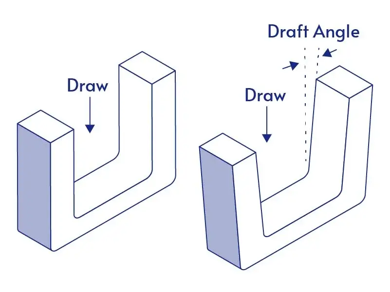
A chamfer is an angled cut at the edge of a part, typically formed at a 45-degree angle, although other angles are possible depending on the design specifications. Chamfers are primarily used to remove sharp edges or to facilitate assembly, especially for parts that will be bolted or screwed together. It is denoted by its size and angle, for example, C1.0 x 45°, meaning a 1.0 mm cut at 45 degrees.
Advantages of Chamfers
- Simplifies deburring by removing burrs and sharp edges efficiently during manufacturing.
- Aids in assembly by providing lead-in surfaces for easier insertion of components like bolts or pins.
- Reduces machining time as it can be produced with standard end mills or chamfer tools.
- Lowers production costs in large batches due to straightforward geometry.
- Improves edge protection in sheet metal parts, preventing damage from impacts.
Disadvantages of Chamfers
- Chamfers do not alleviate stress concentration points and may even contribute to localized stress under certain conditions, potentially affecting the part’s durability.
- Chamfers are not suitable for applications requiring smooth fluid flow, as their angular edges may disrupt the material’s movement.
Key Differences Between Fillet and Chamfer
The choice between fillet and chamfer depends on the part’s function, manufacturing method, and structural needs. Here are the main differences:
1. Geometry
- Fillet: Creates a smooth, curved transition between surfaces, either concave or convex.
- Chamfer: Forms a straight, angled edge that truncates corners. Typically polygonal, often at 45°, though the angle can be adjusted.
2. Function
- Fillet: Reduces stress concentration, improves material flow in processes like injection molding, and enhances structural strength.
- Chamfer: Helps with part alignment and assembly, eases installation of bolts or screws, and minimizes sharp edges for safer handling.
3. Stress Distribution
- Fillet: Distributes forces evenly across the transition, significantly lowering peak stress at corners.
- Chamfer: Reduces stress at sharp edges but is less effective than a fillet for load distribution.
4. Manufacturing Considerations
- Fillet: Requires curved tool paths and specialized tooling (e.g., ball-end mills), which can increase machining time and wear.
- Chamfer: Uses straight cuts with standard tools, making it quicker and less costly to produce.
5. Cost and Time
- Fillet: Higher processing cost due to tool complexity and longer machining paths.
- Chamfer: Lower cost and faster production.
6. Ergonomics
- Fillet: Rounded edges provide safer and more comfortable contact for handling.
- Chamfer: Safer than sharp corners but still has distinct edges.
7. CAD and Design Standards
- Fillet: Specified by radius (e.g., R3, R6) and applied using CAD’s fillet features. Can be a constant or variable radius.
- Chamfer: Defined by angle, distance, or two distances (e.g., 2×45° or 1×1). Applied via CAD chamfer tools for precise edges.

How to Choose Between Fillet and Chamfer?
Choosing between fillet and chamfer is not just a geometric decision—it directly affects part strength, manufacturability, assembly performance, and cost. The right choice depends on how the part will be used, produced, and assembled.
When to Use a Fillet
Use fillets when strength, durability, or material flow is important.
Fillets are recommended for:
- Load-bearing or high-stress areas (brackets, frames, ribs)
- Parts under vibration or cyclic loading
- Injection-molded or cast parts that require smooth material flow
- Thin-wall designs, where sharp corners can lead to cracks
- Products requiring smooth, safe, and premium-looking edges
Why Choose a Fillet?
- Reduces stress concentration and improves fatigue life
- Improves plastic flow and reduces molding defects
- Enhances surface finish and user safety
Practical rule: Use a fillet radius ≥ 0.5 × wall thickness in thin sections.
When to Use a Chamfer?
Use chamfers when assembly, machining efficiency, or edge protection is the priority.
Chamfers are recommended for:
- Bolt holes, threaded holes, and pins (lead-in for assembly)
- Shafts, gears, and mating parts that need alignment
- CNC-machined parts where cycle time matters
- Sheet metal edges that require deburring
- High-volume production where cost control is critical
Why Choose a Chamfer?
- Speeds up machining with simple straight cuts
- Helps guide parts during installation
- Removes sharp edges and burrs efficiently
- Reduces production cost in large batches
Common standard: A 45° chamfer is the most widely used for general-purpose edge breaking and assembly.

Conclusion
Understanding fillet vs chamfer enables better part optimization. Fillets provide strength and flow benefits, while chamfers offer assembly ease and cost savings. Incorrect selection can lead to increased production time, higher costs, or reduced part durability. Jiangzhi specializes in custom parts manufacturing, offering expertise in these features for various industries. Contact us for tailored solutions.