Snap fit design is widely used in product manufacturing due to its simplicity, cost-effectiveness, and ability to create clean, fastener-free assemblies. Plastic part snap fit design due to its numerous benefits, such as reduced assembly time, lower production costs, and the ability to disassemble parts easily. In this post, we will explore the types of snap fits, key snap fit design considerations, the pros and cons of designing snap fits, and how they are commonly used in injection moulded services for efficient and cost-effective assembly.
What is Snap Fit Design?
Snap fit design is a method used to join two components by creating interlocking features that allow them to be snapped together securely. They typically consist of a small protrusion like a stud, hook, or bead on one component that deflects during assembly to catch a feature in the mating component, allowing for easy connection. Plastic snap design is simple and efficient for assembling parts without the need for additional fasteners like screws or adhesives.
The snap fit design guide aims to join components without additional fasteners, allowing for quick assembly and disassembly, reducing manufacturing costs, improving product aesthetics, and enabling more efficient production processes.
The best plastics for injection molding snap fits are ABS, which offers a good balance of strength and flexibility; polycarbonate for high strength and impact resistance; nylon for excellent fatigue resistance; POM (Acetal) for low friction and dimensional stability; and PETG for applications requiring more bending.
Components of Snap-Fit Connections Snap-fit
connections are essential in various applications, allowing for efficient assembly without additional fasteners. These connections typically involve two main components: the base part and the assembly part.
Base Part
The base part is generally larger and more stationary than the assembly part. It can be either a single component or an assembly itself, serving as the reference point for the connection. For example, in automotive design, the car body acts as the base part for various trim components that require assembly.
Assembly Part
The assembly part is usually smaller than the base part and can be handled easily during the assembly process. This component moves during assembly and ultimately connects with the base part.
Functional Elements of Snap-Fit Connections
To ensure the reliability of snap-fit connections, two main functional areas are identified: positioning elements (positioners) and locking elements (lockers). Together, these components form a secure connection between the base part and the assembly part.
Positioners
Positioners are relatively rigid constraint elements that ensure precise alignment between the base and assembly parts while providing resistance to separation beyond just the locking force. They bear most of the load during the constraint process.When a component features positioners, another component will have corresponding positioners, forming a positioning pair.
Lockers
Lockers are constraint elements that deform elastically during assembly and revert to their original shape once assembled, thereby forming a lock and providing holding force.
How Can Stress be Reduced in A Snap Fit?
Stress in Injection snap fits can be reduced by adding fillets at the base of cantilevers, tapering the design for even stress distribution, increasing clip width, avoiding sharp corners, and using materials with appropriate flexibility and strength.
Types of Snap Fit Design
Cantilever Snap Fits
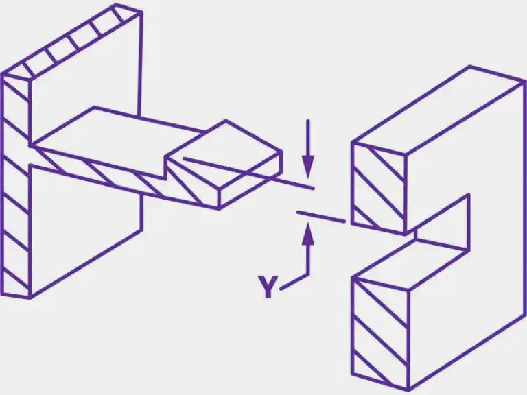
- Cantilever Snap Fits Design
Cantilever injection molding snap fit, the most common and versatile type, feature a flexible beam with a tapered hook at the end that deflects during assembly to catch onto a corresponding recess in the mating part. This design can be adapted for both permanent and releasable connections, making it suitable for a wide range of applications from electronics to automotive components. The variations include straight, U-shaped, and L-shaped cantilevers.
Annular Snap Fits

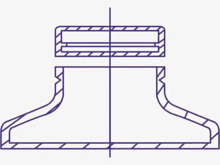
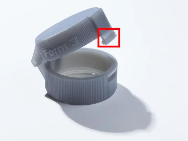
- Annular Snap Fit Design
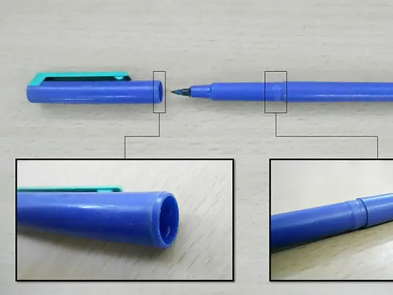
Annular snap fit are specifically designed for joining circular or cylindrical parts, utilizing a circumferential ridge or bump that mates with a corresponding groove. This type of snap fit is frequently seen in everyday items like pen caps, container lids, and lamp housings, though it requires more complex calculations to determine assembly forces accurately.
Torsional Snap Fits

- Torsion Snap Joints Design
Torsional snap fits operate on a different principle, employing a twisting motion rather than bending to create the connection. These designs typically incorporate a spring-loaded lever that snaps into place when pressed, offering a separable connection that’s particularly useful for fastening hinged lids on containers or creating easily accessible compartments in electronic devices.
U-Shaped Snap Fits

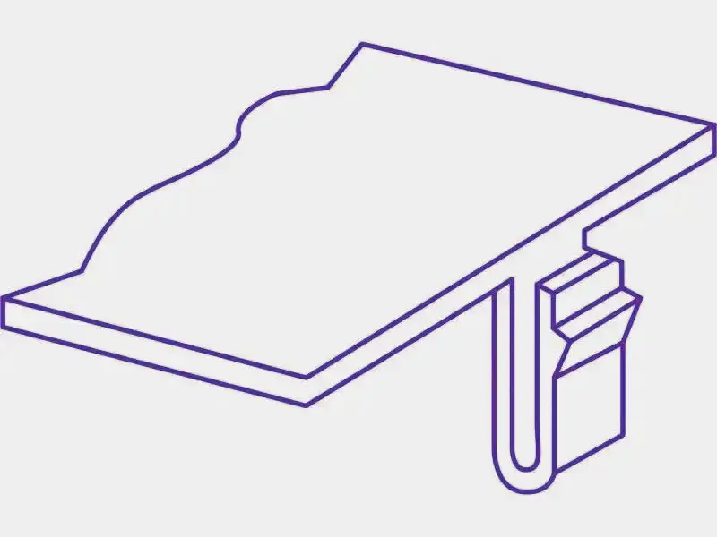
- U Shaped Snap fits Design
U-shaped snap fits, a variation of the cantilever design, allow for longer cantilevers to be incorporated into compact spaces. By distributing the deflection force over a larger area, U-shaped snap fits can provide lower assembly forces and are often utilized along the edges of parts. This design can be particularly advantageous in injection molding processes, potentially eliminating the need for complex sliding mechanisms in the mold.
Snap Fits Design Considerations and practices
Designing effective injection molding snap fits involves several critical considerations to ensure the assembly performs well under various conditions. These include material selection, stress and strain analysis, tolerance and fit, assembly and disassembly forces, and environmental factors.
Material Selection Considerations:
Choose materials with sufficient elasticity to allow for temporary deformation during assembly without permanent damage. Thermoplastics like ABS, polycarbonate, and nylon are commonly used due to their balance of rigidity and flexibility. Consider environmental factors like temperature, chemical exposure, and UV resistance when selecting materials. Evaluate the material’s fatigue resistance, especially for snap fits that will be frequently assembled/disassembled.
Stress and Strain Analysis:
Analyze maximum bending stress and strain to ensure the snap fit can withstand assembly forces without failure. Add fillets at the base of cantilever snap fits to reduce stress concentration. The fillet radius should be at least 0.5 times the cantilever thickness. For injection molding, consider draft angles and undercuts to ensure parts can be easily removed from molds.
Dimensional Tolerances and Clearances:
Maintain tight tolerances to ensure proper engagement and retention force. Use general guidelines for clearances: 0.2 mm for tight fits, 0.3 mm for close-fit snap joints, 0.4 mm for slide fits. Account for material shrinkage and thermal expansion in tolerance calculations. Design for manufacturability by considering molding and machining capabilities.
Assembly and Disassembly Forces:
Calculate insertion and retention forces based on geometry and material properties. Increase the width of clips or hooks to enhance strength and stiffness. A minimum width of 5 mm is recommended for plasatic snap fit designs. Design for appropriate assembly force, too high assembly force can cause damage, and too low assembly force may result in accidental disassembly. Consider the number of assembly/disassembly cycles the snap fit must withstand. Incorporate features like chamfers or lead-ins to guide assembly and reduce insertion force.
Snap Fit Design Calculations
Snap fit design calculations are crucial for creating effective and reliable snap fit joints. Here’s an overview of the key calculations for cantilever snap joints, which are the most common type:
Maximum bending stress:
σmax = mc / I
Where:
M is the maximum bending moment
c is the distance from the point of interest to the neutral axis
I is the moment of inertia
Maximum strain:
ε = M / IE
Where:
E is Young’s modulus of the material
Deflection for a constant cross-sectioned beam:
y = 0.67 * εl² / h
Where:
l is the length of the beam
h is the thickness at root
Deflection force:
P = bh² / 6 * Es ε / l
Where:
b is the width at root Es is the secant modulus
Mating force:
W = P * (μ + tan(σ)) / (1 – tan(σ))
Where:
μ is the coefficient of friction σ is the angle of inclination
For a sample calculation, consider a cantilever beam with:
Arm length (l) = 20 mm
Width (b) = 10 mm
Undercut (y) = 3 mm
Angle of inclination = 30°
Material: ABS (Es = 1350 N/mm²)
Calculating thickness (h):
h = 0.67 * 0.25 * 20² / 3 = 2.23 mm
Calculating deflection force (P):
P = 10 * 2.23² / 6 * 1350 * 0.25 / 20 = 13.98 N
Calculating mating force (W):
W = 13.98 * (0.72 + tan(30)) / (1 – tan(30)) = 42.91 N
Common Applications of Snap Fit Design
Design snap fit is widely used across various industries due to its versatility, cost-effectiveness, and ease of assembly. Here are some key applications in different sectors:
Toys: Snap fits are extensively used in the toy industry. Toys need to be lightweight, cost-effective, and suitable for mass production. Effective snap fit design guide is the idea choice due to without additional fasteners, simplifying assembly and reducing production costs.

- Annular Snap Fits in Plastic parts
Pens: The annular snap joint in pen caps is a classic example in our daily. Strap buckles: Snap fit design in buckles allows for quick and secure fastening and unfastening. Such as in safety harnesses or outdoor gear.

- U Shape Snap Fit in Plastic Parts Application
Enclosures: Many electronic enclosures, such as USB hubs and Ethernet boxes, use snap fit joints to secure the housing components. Snap fits provide a clean, screw-free appearance and simplify the assembly process.

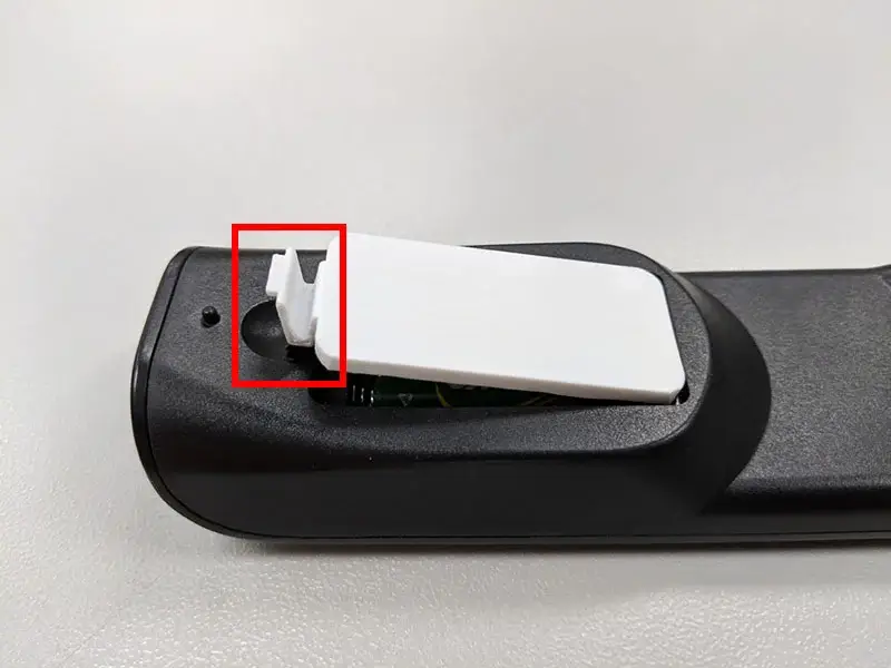
- Battery Covers
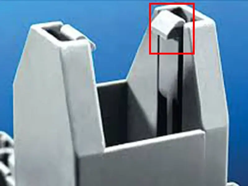
Lids and covers: U-shaped snap fittings in lids and covers provide a secure closure that can withstand repeated use. They are easy to open and close.

- Torsional Snap Fits in Plastic Parts Application
3D print snap fit designs: In the realm of 3D printing, using bolts and fasteners can compromise the structural integrity of thin-walled designs, making snap fits a preferable alternative to joining parts without compromising structural integrity.
Advantages and Disadvantages of Snap Fit Design
Based on the search results and the query about advantages and disadvantages of snap fit design, here’s a summary:
Advantages of Snap Fit Design:
- Economical: Injection molding snap fits can be directly molded on plastic parts, eliminating the need for additional fasteners like screws or nuts, saving costs.
- Effective: The connection strength of snap fits can meet most product design requirements.
- Simple and convenient: With proper design, snap fits enable quick assembly and disassembly, often without additional tools.
- Aesthetic integrity: Snap fits maintain the product’s appearance, making them popular in consumer electronics.
- Reduced part count: Snap fits integrate joining features into components, reducing the overall number of parts.
Disadvantages of Design Snap Fit:
- High precision requirements: Snap fits need high precision in fitting, often requiring multiple trial mold adjustments.
- Limited reusability: Most snap fits have limited disassembly cycles, as frequent disassembly can cause deformation and reduce effectiveness.
- Sensitivity to material properties: The performance of snap fits is highly dependent on the specific material characteristics.
- Not ideal for heavy-duty applications: Snap fits may not be suitable for applications requiring very high strength or load-bearing capacity.
- Risk of permanent deformation: Overloading or frequent use can lead to permanent deformation of the snap fit components.
Conclusion
Design snap fit is a versatile and cost-effective joining method that has become integral to modern product development across various industries. By carefully considering the principles and best practices of plastic snap fit design guide, engineers can create more efficient, durable, and user-friendly products.

