
Automotive lighting parts must meet strict requirements for optical performance, dimensional accuracy, surface quality, and long-term durability. A headlamp lens may look clear after molding, but stress patterns, microscopic defects, or dimensional deviations can become visible during optical testing or after subsequent coating and metallization.
These requirements make automotive lighting injection molding more demanding than conventional plastic part production. Components such as PC and PMMA lamp lenses, decorative bezels, two-color tail lamps, and Adaptive Driving Beam (ADB) lenses require careful control of material condition, mold design, filling behavior, cooling, and post-molding processes.
Material Processing Limitations: PC and PMMA Optical Polymers
Automotive lighting covers and thick-walled lenses primarily utilize optical-grade Polycarbonate (PC) and Polymethyl Methacrylate (PMMA). While these polymers deliver high light transmittance and impact resistance, their narrow processing windows present significant molding risks.
Moisture Sensitivity and Silver Streaks
PC and PMMA are sensitive to moisture during melt processing. If the resin is not dried adequately, residual moisture can cause hydrolytic degradation at processing temperatures. Vapor and degradation products may also contribute to silver streaks, bubbles, and other surface defects.
PC requires strict drying down to a moisture content of less than 0.02% at 120℃ for at least 4 hours before processing. If trace moisture enters the melt barrel, it vaporizes rapidly under high processing temperatures, forming silver streaks, micro-bubbles, and internal hazing that ruin light transmission.
High Melt Viscosity and Residual Stress
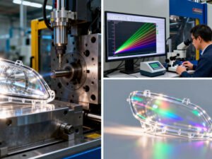
PC exhibits high melt viscosity and poor flowability, requiring high injection pressures to fill long-flow paths. However, excessive shear forces and non-uniform cooling induce high internal residual stress. Under polarized light or sunlight, this stress manifests as optical birefringence (rainbow patterns). Residual stress causes catastrophic cracking or coat-stripping during secondary downstream processes, such as vacuum aluminization, UV hard-coating, or thermal shock testing. This issue is particularly acute in thick-walled ADB matrix lenses, which often require post-mold annealing treatments to relieve stress.
Thermal Degradation and Carbon Contamination
Optical polymers degrade rapidly when exposed to excessive residence times at elevated barrel temperatures. Carbonized resin particles or foreign contaminants produce visible black specks, resulting in high scrap rates for transparent optical components.
Manufacturing controls include:
- Managing material residence time and avoiding unnecessary thermal exposure.
- Maintaining clean barrels, screws, hoppers, and material conveying systems.
- Controlling material changes and purging procedures.
- Inspecting molded parts for contamination under appropriate lighting conditions.

Zero-Tolerance Optical and Surface Finish Standards
While minor flow lines or weld marks may be acceptable in structural automotive parts, optical lighting components demand absolute surface perfection. Light amplification makes even microscopic defects instantly visible.
Flow Marks, Weld Lines, and Jetting
Large headlamp lenses and full-width tail lamps often have broad curved surfaces and long flow paths. If the melt front advances unevenly, visible flow marks or waviness may develop. Jetting occurs when the melt enters the cavity as a narrow stream instead of forming a stable advancing flow front.
For optical components, a weld line is not necessarily just a cosmetic issue. Depending on its location and characteristics, it may scatter light, create visible lines, or affect optical performance. Critical optical zones may therefore require strict restrictions on weld-line location or acceptance.
Replicating Micro-Optical Geometries
Taillight lenses and ADB matrices incorporate micrometer-scale optical textures, Fresnel structures, and light-guide teeth. Filling these intricate micro-features requires a highly stable, uniform melt-front velocity. Slight fluctuations in injection speed or mold surface temperature result in incomplete filling or distorted tooth geometries, directly altering the intended light path and causing laboratory photometric testing failures.
Stringent Venting Requirements
Trapped gas in transparent molds does not merely cause localized burning; it leaves visible gas streaks and micro-haze. Precision venting channels—typically 0.0mm to 0.02 mm deep—must be placed along parting lines and melt-flow ends. Exceeding these vent depth tolerances causes heavy flash.
Large Curved Surfaces, Wall Thickness Variation, and Warpage
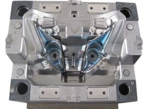
Modern headlamp lenses and full-width tail lamps often use large, freeform surfaces with varying wall thickness. These geometries create challenges in filling, packing, cooling, shrinkage, and dimensional stability.
- Sink Marks vs. Short Shots: Thicker sections may develop sink marks or internal voids if shrinkage is not adequately compensated. Thin sections or restricted flow areas may be difficult to fill. Differences in cooling rates and molecular orientation can also cause uneven shrinkage and warpage after ejection.
- Thermal Creep and Deformation: Non-uniform cooling rates and inconsistent molecular orientations cause parts to creep and warp after ejection.
- Sealing and Clearance Failures: Automotive lighting assemblies are hermetically sealed units. A surface contour deviation of just 0.1 mm disrupts housing seal alignment, leading to moisture ingress, lens fogging, and environmental seal failure.
High Requirements for Mold Manufacturing, Polishing, and Temperature Control
The mold has a direct influence on optical surface quality, dimensional accuracy, and production consistency. For automotive lighting, mold manufacturing often requires more precise surface finishing and thermal management than conventional structural plastic parts.
Optical Mirror-Finish Polishing
- Cavity surfaces must be polished to SPI A-2 or equivalent high-precision mirror-finish grades using premium corrosion-resistant mold steels such as S136 or STAVAX.
- Eliminates microscopic sanding lines, machining tool marks, and surface roughness that scatter light rays and cause optical distortion or haze.
Uniform Conformal Cooling (Thermal Management)
- Molds incorporate advanced conformal cooling channels that contour closely to the complex 3D optical profile, maintaining precise mold wall temperatures between 110℃ and 130℃ (particularly for PC optical covers).
- Ensures even thermal dissipation across large curved surfaces, preventing localized hot spots, differential shrinkage, flow marks, and internal stress gradients.
Advanced Ejection and Draft Engineering
- Standard small ejector pins are replaced with stripper plates, large-area ejector blocks, and angled lifters to distribute release forces evenly. Component designs require increased draft angles of 1.5° – 3.0°.
- Prevents visible ejector pin marks, surface whitening, and structural scoring on transparent optical faces during part release.
Special Challenges in Dual-Color and Multi-Shot Molding
Modern rear lamp assemblies widely adopt multi-material or multi-color injection techniques (e.g., combining transparent PC with red PMMA or black ABS).
Material Washout and Bleeding (Color Contamination)
During the second injection phase, high-temperature molten resin flows over the semi-finished first-shot substrate. If temperatures or injection velocities are mismanaged, the second shot melts and washes away the edge of the first material, creating unsightly color bleeding or dark streaks along the boundary line.
Rotary Mold Positioning Accuracy
In rotary or rotating-platen systems, the mold must return to the correct position for the second shot. Positioning errors can cause misalignment between the two materials, uneven interface lines, or leakage at the sealing boundary.
Interface Bonding and Differential Shrinkage
Different materials may have different shrinkage rates, thermal expansion behavior, and bonding characteristics. If these differences are not addressed, the interface may warp, crack, or lose adhesion during cooling or subsequent environmental exposure.
Material compatibility also matters when the component undergoes vacuum metallization, UV coating, or thermal cycling. A successful initial molding trial does not necessarily establish long-term interface reliability.
Secondary Coating Defect Amplification
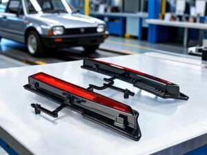
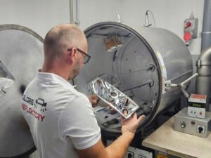
Injection molding is only the initial phase in manufacturing an automotive lamp. Molded components undergo downstream secondary processing, such as high-vacuum aluminum metallization and UV-cured hard coating.
Secondary surface coatings act as visual amplifiers. Microscopic surface pitting, outgassing voids, or invisible stress lines within the molded plastic instantly become visible after metallization or spray coating. Furthermore, high internal stress reduces coating adhesion, causing premature paint flaking and delamination during environmental stress screening.
Partnering with Jiangzhi for Automotive Lighting Injection Molding
Manufacturing automotive lighting components successfully requires a unified approach combining advanced tool engineering, scientific process validation, and strict quality assurance.
At Jiangzhi, we support automotive lighting parts customization and OEM engineering teams with precision custom injection molding, optical tool building, and comprehensive Design for Manufacturability (DFM) reviews. Contact our engineering team today to review your technical drawings (STEP, IGS, or PDF) for a professional DFM analysis and production quote.


