Design and Engineering Guidelines
Proper design of countersink holes requires attention to several factors:
Angle matching: always select a countersink angle that matches the fastener head exactly.
Diameter clearance: the top diameter of the countersink should be 0.2–0.5 mm larger than the fastener head to account for tolerances and plating.
Depth control: the cone depth should allow the head to sit flush or 0.1–0.2 mm below the surface. Excessive depth weakens the surrounding material.
Edge distance: Maintain sufficient material between the countersink and the part edge to prevent cracking, especially in thin sheets.
Tolerance and specification: Use CAD built-in countersink features when possible. On drawings, specify as: ⌵ Ø 8.5 × 90° × depth 2.5 mm.
Material considerations: softer materials may require slightly larger clearances to prevent galling during installation.
Manufacturing Methods for Countersink Holes
Countersink holes can be produced using several manufacturing approaches, depending on material, tolerance requirements, and production volume.
CNC Machining
Computer-controlled milling or drilling centers produce the most accurate countersink holes. Separate tools or programmed toolpaths allow precise control of angle, diameter, and depth. This is the preferred method for metals, composites, and high-precision parts.
Injection Molding
Pre-designed mold cavities form countersink holes directly during the molding process. Proper draft angles, wall thickness, and cooling control ensure accurate shape and consistent dimensions. This method is ideal for high-volume plastic parts where post-machining is impractical.
Manual and Semi-Automated Machining
In lower-volume production or prototyping, countersinking a hole may be performed using drill presses or handheld tools. While this approach is flexible, it is more sensitive to operator technique and tool condition, which can affect surface finish and dimensional consistency.
Drill and Countersink Combination Tools
A single tool drills the pilot hole and forms the cone in one operation. This method is efficient for manual or small-batch production in wood, plastic, and softer metals.
Sheet Metal Forming
In sheet metal, countersink holes are often created by pressing a tapered punch into the material. This displaces rather than removes material, producing consistent results with low tooling cost.
PCB Fabrication
Printed circuit boards use controlled-depth milling or specialized drills to create countersink holes. The process must be carefully managed to avoid damaging internal layers.
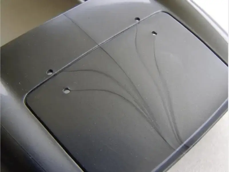
Countersink Holes in Injection-Molded Plastic Parts
Countersink holes can be molded directly into plastic parts, eliminating secondary machining and improving assembly efficiency. Unlike metal machining, molded countersinks must be designed with material flow, shrinkage, and mold structure in mind.
Key design considerations include:
- Direct molding: Formed using tapered core pins, allowing parts to be assembly-ready
- Draft & angle control: Draft may slightly affect the seating angle and must match the fastener
- Wall thickness: Avoid thick sections around the countersink to reduce sink marks
- Ejector layout: Keep ejector pins away from the seating surface
- Gate location: Ensure stable flow to prevent weld lines or incomplete filling
With proper design, molded countersinks provide a clean, reliable fastening solution without additional processing.
Advantages and Value of Countersink Holes
The use of countersink holes provides several practical advantages in engineering and manufacturing.
- From a functional standpoint, countersink holes allow fasteners to sit flush with the surface, reducing interference with moving parts or mating components.
- From a structural perspective, proper countersinking improves load distribution between the fastener and the part. When the contact surface is uniform, the joint is less prone to loosening or localized deformation.
- Countersink holes also contribute to safety and usability. Flush-mounted fasteners reduce sharp edges and minimize the risk of snagging or abrasion during handling or operation.
- Finally, in products where appearance matters, countersink holes provide a cleaner and more uniform surface without raised fastener heads.
Common Applications of Countersink Holes
- Aerospace: Fasteners sit flush with aircraft skin to reduce drag and prevent snagging on adjacent components.
- Automotive: Countersunk screws in interior panels ensure smooth surfaces and prevent interference with moving parts.
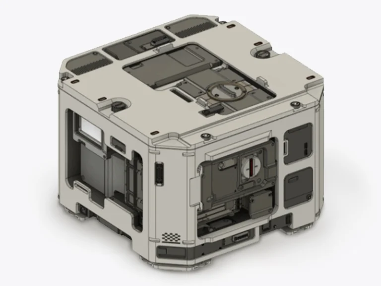
- Electronics: Flush-mounted fasteners in enclosures reduce short-circuit risk and improve appearance.
- Furniture/Woodworking: Countersinking prevents screw heads from splitting wood and provides a clean finish.
Conclusion
Properly designed countersink holes not only simplify assembly but also enhance safety, reliability, and product appearance. They are widely used in industries ranging from aerospace and automotive to electronics and furniture, proving their versatility and functional importance. If you’re designing plastic parts with countersink holes, getting the angle, depth, and wall thickness right is critical for both performance and manufacturability.
At Jiangzhi, we support custom plastic injection molding with engineering guidance from DFM review to final production—helping you integrate features like countersinks directly into your molded parts without secondary machining. Send us your drawings or requirements, and our engineers will help you optimize your design for reliable and cost-effective production.
FAQ