Molded part corner design plays a pivotal role in the overall performance and manufacturability of molded parts. Properly designed corners can significantly enhance the structural integrity, aesthetics, and functionality of a part. In contrast, poorly designed corners can lead to a range of issues. In this post, we will explore plastic molded part corner design tips and considerations to create more efficient, reliable, and aesthetically pleasing molded parts.

Why Corner Design Matters
Regardless of which corner form is used, corner design influences part performance in five key ways:
- Stress Distribution: Corners are where stress tends to concentrate most; poor treatment here is a common starting point for part failure.
- Material Flow: The corner profile directly shapes how molten plastic flows; a poor profile can cause short shots, weld lines, or trapped air.
- Part Ejection: Corner treatment affects whether a part sticks in the mold, which in turn affects ejection damage, cycle time, and mold life.
- Mold Manufacturability: Different corner profiles require different machining approaches, directly affecting mold cost and lead time.
- Aesthetics: Corner treatment has a direct impact on the likelihood of sink marks, flow lines, and other surface defects.
Types of Corners in Molded Parts
Corner types are typically described along two axes: position (external vs. internal) and profile (sharp, rounded, or flat-transition). A single part usually combines several of these. Here’s an overview of the main types:
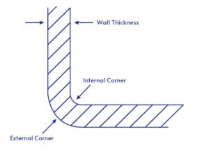
External Corners:
These are the outer corners of a part. They are typically designed with a radius to improve strength and manufacturability. The recommended radius usually ranges from 0.5 to 2 times the wall thickness.
Internal Corners:
These are the inside corners of a part. They are often designed with fillets to reduce stress concentration and improve material flow. The internal radius is typically smaller than the external radius to maintain uniform wall thickness.
Sharp Corners:
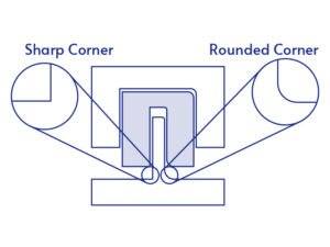
While generally avoided due to stress concentration issues, sharp corners are sometimes necessary, especially at parting lines. They can be challenging to manufacture and may require special considerations in mold design.
Rounded Corners:
These are corners with a significant radius, used to distribute stress, improve material flow, and enhance part strength. They are preferred in most injection molding designs.
Radiused Corners:
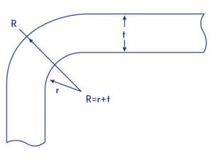
Similar to rounded corners, these have a specific radius applied to reduce stress concentration and improve moldability.
Filleted Corners:
These are internal corners with a concave radius transition, used to reduce stress concentration and improve material flow.

Chamfered Corners:
While not strictly a “rounded” corner, chamfers are sometimes used instead of radii, especially in parts where a specific edge profile is required. Designers should evaluate whether a rounded corner or beveled edge is more suitable for the application. For a detailed comparison between these two approaches, see our guide to Fillet vs Chamfer Design.


Guidelines for Molded Part Corners Design
The general corner design principle is: use rounded corners instead of sharp ones whenever possible. The recommended corner radii are related to different materials and the molded part’s wall thickness. They are usually expressed as “radius = N × wall thickness.” Internal radii are generally smaller than the external radius at the same location.
Recommended Radii for Different Materials
| Material Type | Recommended Minimum Radius (relative to wall thickness) | Notes |
|---|---|---|
| Thermoplastics | 0.5–1.0× | Suitable for most common materials |
| Thermosets | 1.5–2.0× | More brittle; larger radii needed to disperse stress |
| Elastomers | ≥0.5× | More flexible; radius requirements are relatively relaxed |

Optimal Corner Radii Based on Part Thickness
| Wall Thickness | Recommended Radius |
|---|---|
| Thin (< 2 mm) | 0.5–1.0× wall thickness |
| Medium (2–4 mm) | 1.0–1.5× wall thickness |
| Thick (> 4 mm) | 1.5–2.0× wall thickness, to prevent sink marks and similar defects |
Factors to Consider Alongside Corner Radius
Corner radius is not an isolated parameter — it needs to work together with other design elements:
- Draft angle: Even a well-designed radius can still cause ejection issues if draft is insufficient. See our Injection Molding Draft Angle Guide for recommended values.
- Overall wall thickness strategy: Both internal and external corner radii should serve the broader goal of uniform wall thickness, avoiding localized material buildup. See our Wall Thickness Design Guide for detailed recommendations.
- For a fuller picture of plastic part design, including wall thickness, ribs, bosses, holes, draft angles, and more, see our comprehensive Plastic Part Design Guideline.
Why Are Rounded Corners Used in Design?
Rounded corners in injection-molded parts offer numerous benefits that significantly improve both the manufacturing process and the quality of the final product. Let’s explore these benefits in detail:
Improved Stress Distribution
Rounded corners distribute stress more evenly across the part, reducing stress concentration. This even distribution helps prevent localized weaknesses that could lead to part failure. The stress reduction factor can be significant; for example, a corner with a radius equal to the part thickness can reduce stress by up to 75% compared to a sharp corner.
Enhanced Mold Filling and Material Flow
Rounded corners facilitate smoother material flow during the injection process. This improved flow results in more consistent filling of the mold cavity, Reduced risk of short shots or incomplete filling, lower injection pressures, which can extend mold life, and more uniform cooling, leading to less warpage and better dimensional stability. Better flow also means fewer issues with weld lines, air traps, and other flow-related defects.
Easier Part Ejection
Parts with rounded corners are less likely to stick in the mold during ejection. This leads to reduced cycle times, improved production efficiency, less damage to parts during ejection, decreased wear on mold components, extended mold life, and more consistent part quality across production runs.
Increased Part Strength and Durability
Rounded corners significantly enhance the overall strength of the part. They improve impact resistance by distributing impact forces more evenly. This increased strength means higher load-bearing capacity, better fatigue resistance, improved long-term durability, and reduced likelihood of part failure in service. Studies have shown that increasing an internal corner radius from 0.010 in. to 0.020 in. can improve impact strength by up to roughly 25% in some materials.
Additional Benefits
Improved Aesthetics: Rounded corners often provide a more polished, professional appearance.
Enhanced Safety: For consumer products, rounded corners reduce the risk of injury from sharp edges.
Better Mold Manufacturability: Rounded corners are easier to machine in mold steel, potentially reducing mold cost.
Material Savings: In some cases, the improved strength from rounded corners allows for thinner overall wall sections, reducing material usage.
Conclusion
Proper molded part corner design is a critical aspect of creating high-quality, durable, and manufacturable injection molded parts. By applying these best practices and considering the unique requirements of each project, designers and engineers can create parts that are not only visually appealing but also robust, efficient to manufacture, and well-suited to their intended function.
With a well-optimized corner design, your part is ready for the next stage of development. Jiangzhi’s injection molding services support the entire process, from DFM analysis and design optimization to high-quality part production.