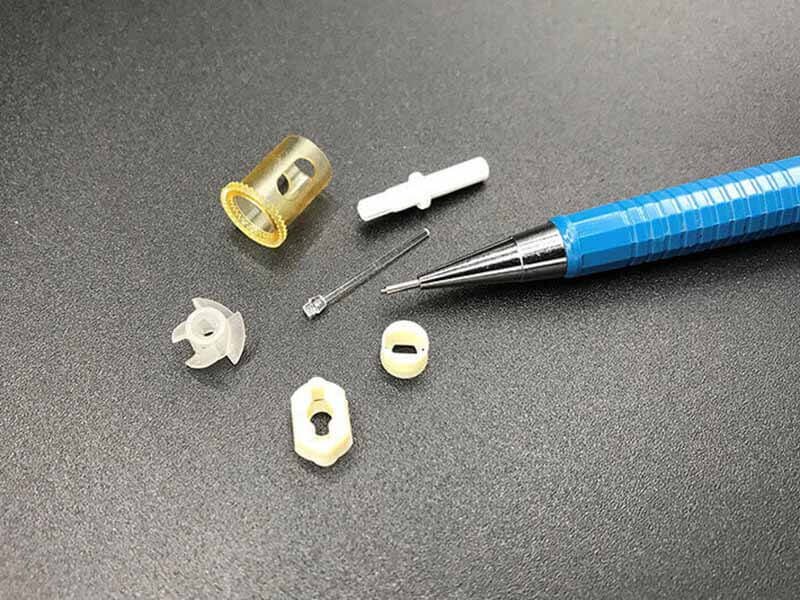
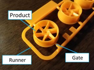
Removing injection molding gate cost is easy to overlook because it rarely appears as its own line on a quote. After the melt fills the cavity, a stub of material remains in the channel the plastic entered through. That channel is the gate, and once a part’s geometry is settled, the gate type and location are largely settled with it.
Ideally, the gate separates on its own as the mold opens or the part ejects. In many real projects, it does not. Cosmetic requirements, material behavior, and the gate type often preclude that option, so the process requires a separate step to remove the gate and preserve the part’s appearance and assembly dimensions.
Any step that exists requires labor, equipment, or time and becomes part of the product’s cost. On a precision part with thin margins, a few cents per piece looks small, but it grows with annual volume. This article explains how gates are removed, when the cost needs to be calculated at all, and how to estimate it for manual removal.
Three Ways to Remove an Injection Molding Gate
Gate removal falls into two groups: cutting inside the mold and removing the gate outside the mold. Outside the mold, the work is either manual or mechanical.
In-Mold Gate Cutting
A mechanism inside the mold separates the gate from the part while the part is still cooling, so the part and runner are already apart when the mold opens. This is the most automated option and creates no separate trimming operation. The tradeoff is tooling: the mold is more complex, the investment is higher, and the gate design has to meet specific requirements. For that reason, the choice is normally fixed during mold and process planning.
Manual Removal
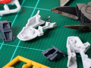
The operator uses a utility knife or hook knife. Once the part has cooled enough to handle, the operator breaks off the gate and cuts the remaining stub at its base, holding the blade perpendicular to the part. The motion should be slow, steady, and done in one cut to avoid a second cut that leaves a step and to prevent stress whitening around the cut. The advantages are no equipment investment and the flexibility to adjust when production conditions change. The disadvantages are low throughput, poor consistency, and a tendency toward over-trimming or under-trimming.
Mechanical Trimming
A fixed, straight blade holder cuts the gate while the take-out robot moves the part past it in one direction. Punching fixtures work on a similar principle for fixed gate positions. This method is simple and efficient, which suits high volumes. The gate has to lie in a straight line, though, and blade strength is limited, so it works best on softer materials such as PP. The gate type decides which methods are practical:
| Gate Type | Typical Removal Approach | Notes |
|---|---|---|
| Side (edge) gate | Hand nippers, knife, or punching | Visible scar on the side wall; cosmetic parts may need polishing |
| Pin-point gate | Separates automatically in a three-plate mold | Minimal mark; light grinding for high-appearance parts |
| Submarine (tunnel) gate | Separates automatically on ejection | Hidden on a non-visible surface; brittle materials can chip at the root |
| Fan gate | Punching or milling | Wide, thin gate on large thin-wall parts; hard to trim by hand |
| Direct (sprue) gate | Sawing and polishing | Large cross-section and heavy mark; suited to thick parts with low cosmetic demands |

When Does Gate Removal Cost Need to Be Calculated?
This question determines whether the calculation is needed at all.
In typical automated production, mechanical trimming is not a separate operation. The take-out robot removes the part and passes it through the blade in the same motion, so the gate is cut with almost no added cycle time and no dedicated labor. That cost already sits inside the robot and the molding cycle, and charging it again as gate removal would count it twice. Blade wear and depreciation of the trimming fixture are different. They are material and equipment costs, and they still belong in the product’s manufacturing cost.
Only manual removal creates a separate, measurable labor cost. That is the case the model below covers.
How to Estimate Manual Gate Removal Cost
Manual gate removal cost depends mainly on part size, the number of gates, and gate size. The method first works out the labor time consumed per part, then multiplies by the direct labor rate.
Gate removal labor cost = Labor time × Direct labor rate
Labor time = Pick-up time + Put-down time + (Number of gates × Gate change time) + (Number of gates × Gate width ÷ Cutting speed)
Pick-Up and Placement Time
Pick-up and put-down time depends on part size. Larger parts take longer to handle. For preliminary estimation, a simple reference table can be used:
| Part Characteristic Size L | Pick-Up Time | Placement Time |
|---|---|---|
| ≤ 50 mm | 0.5 s | 0.5 s |
| 50–200 mm | 1.0 s | 1.0 s |
| 200–400 mm | 1.5 s | 1.5 s |
| 400–600 mm | 2.0 s | 2.0 s |
| 600–800 mm | 2.5 s | 2.5 s |
| 800–1000 mm | 3.0 s | 3.0 s |
Gate Quantity
Number of gates follows from the melt flow length relative to wall thickness. Materials that flow poorly, such as PC, rigid PVC, and PMMA, need more feed points than medium-flow materials such as ABS, POM, and PS, which in turn need more than free-flowing materials such as PP, PE, and PA. The L/T ratio, where L represents flow length and T represents wall thickness, can be used as an initial reference when considering the number of injection points. and not the only criterion.
Gate Change Time and Cutting Speed
These cover the positioning motion for each gate and the pace of the cut. Both are empirical values that vary with operator skill.
Gate Width
Gate size depends mainly on the gate type selected and the mass of the part. The table below gives a quick first estimate by part mass, which can then be adjusted for the specific features of the product:
| Part Mass (g) | Gate Height (mm) | Gate Width (mm) |
| 0–5 | 0.25 | 0.75 |
| 5–40 | 0.50 | 1.50 |
| 40–200 | 0.75 | 2.25 |
| Above 200 | 1.00 | 3.00 |
In the labor-time formula, the cutting stroke depends only on the width of the cut, so gate height does not enter the calculation:
Cutting time per gate = Gate width ÷ Cutting speed
A wider gate means a longer stroke and more time. The number of gates, in turn, multiplies both the change time and the cutting time, which makes gate count the variable that affects labor time most.
Example: Calculating Gate Removal Cost
Take a molded part with a characteristic dimension L of 300 mm and a mass of about 50 g. Fill analysis calls for 2 feed points. For illustration, assume a direct labor rate of $30 per hour; in practice, use your own actual rate. The empirical values used here are 1.5 s each for pick-up and put-down at this part size, 2 s of change time per gate, and a cutting speed of 2.5 mm/s.
Step 1: Pick-up and put-down time. L = 300 mm falls in the 200–400 mm band, which gives 1.5 s each for pick-up and put-down, or 3.0 s in total.
Step 2: Gate width. A mass of 50 g falls in the 40–200 g band, so the gate width is 2.25 mm.
Step 3: Labor time.
- Change time: 2 gates × 2 s = 4.0 s
- Cutting time: 2 × 2.25 mm ÷ 2.5 mm/s = 1.8 s
- Labor time per part: 1.5 + 1.5 + 4.0 + 1.8 = 8.8 s
Step 4: Convert to cost.
- Time in hours: 8.8 ÷ 3,600 ≈ 0.00244 h
- Gate removal cost per part: 0.00244 × $30 ≈ $0.073
Why the Result Is an Estimate, and How to Calibrate It
These methods do not apply equally to every product. Structure, material, and gate type all vary, and accuracy varies with them. There is no universally accepted method for calculating gate removal cost, and simulating labor time precisely remains difficult. The pick-up time, change time, and cutting speed used above are essentially empirical values. Operator skill, the condition of the gate stub, and whether the part needs extra inspection all push real labor time away from the theoretical figure.
The model also covers labor time only. It does not capture scrap and rework when trimming goes wrong, such as whitening or cracks at the gate root, scratches from dull blades, uneven stub height, or distortion from trimming a part that is still warm. Those losses sit in a separate part of the cost.
A more practical approach than treating a general table as the answer is to calibrate it to your own products:
- Group products by category. Build a separate model for parts with similar structure, material, and gate type.
- Measure similar parts in production. Take stable, running parts as samples and record real pick-up, change, and cutting times with a stopwatch.
- Replace assumed parameters with measured ones. Substitute the measured data for the empirical values, redefining parameters such as gate change time and cutting speed.
- Compare and correct continuously. Check the model’s predictions against actual labor cost and adjust, gradually building a parameter library for your product families.
This turns gate removal cost from a rough guess into traceable engineering data.
Ways to Reduce Gate Removal Cost
Most of the cost is set by decisions made before production, so the most effective changes happen in design and tooling.
- Use fewer feed points where filling allows. Gate count affects both change time and cutting time.
- Choose self-severing gates for volume. Pin-point and submarine gates separate during mold opening or ejection, which removes the manual step. They add tooling cost, so they pay off at higher volumes.
- Keep gates off cosmetic surfaces. A gate on a non-visible surface reduces the grinding and polishing needed afterward.
- Match the method to the material. Avoid manual trimming for brittle or transparent parts, and settle the gate design early in mold design.
Conclusion
Estimating injection molding gate cost comes down to three questions: whether the process requires manual work at all, what motions make up the labor time, and how each motion is measured. Separate in-mold from outside-the-mold removal first, since only manual removal gets its own charge. Then apply the labor-time formula and multiply by your own direct labor rate.
If you are comparing gate layouts or weighing manual trimming against in-mold degating for a new part, our guide to injection molding gate types can help you understand the available options. Send us your drawings and expected annual volume. We can review gate removal alongside tooling and cycle time before the mold is cut.