Injection mold design is an important step in plastic product development. The mold structure directly affects product quality, dimensional accuracy, production efficiency, and overall tooling cost. A well-designed mold helps ensure stable production by optimizing key elements such as cavity layout, runner system, cooling channels, and ejection mechanism. It also helps reduce common production risks, including molding defects, frequent mold modifications, and unnecessary maintenance.
What Is Injection Mold Design?
Injection Mold Design is the engineering process of designing the structure, components, and operating mechanisms of an injection mold used in the injection molding process for plastic part manufacturing. It defines how the mold will be built, how plastic material will flow inside the cavity, how the part will cool, and how the finished component will be removed after molding. The primary objectives of injection mold design are stable molding, dimensional accuracy, reliable demolding, manageable manufacturing cost, and long-term maintainability.
Main Components of an Injection Mold
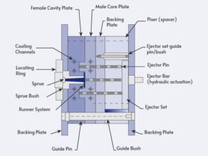
An injection mold generally contains several functional systems. Each system must work with the others because a problem in one area can affect the entire molding operation.
| Mold component | Main function |
|---|---|
| Cavity and core | Form the external and internal surfaces of the plastic part |
| Parting line | Separates the mold halves and affects ejection, flash, and appearance |
| Runner system | Directs molten plastic from the machine nozzle toward the cavity |
| Gate | Controls the entry point of plastic into the cavity |
| Venting system | Allows air and gases to escape during filling |
| Cooling system | Removes heat and controls mold temperature |
| Ejection system | Pushes the molded part away from the core or cavity |
| Guide and locating system | Maintains accurate alignment between mold halves |
| Side-action system | Forms side holes, undercuts, and other features that cannot be released directly |
| Mold base and support system | Holds and supports the functional mold components |
Injection Mold Design Process
The injection mold design process involves multiple engineering steps, from reviewing the product design to testing the finished mold. Each stage affects mold performance, manufacturing cost, and production stability.
Step 1: Product Design Review and Mold Feasibility Analysis
Before starting mold design, engineers need to evaluate whether the product structure is suitable for injection molding. The purpose of this stage is to identify design limitations that may affect mold manufacturing or production performance.
Key factors of plastic part design include:
- Product geometry;
- Wall thickness distribution;
- Draft angle requirements;
- Undercut structures;
- Assembly requirements;
- Surface finish requirements.
Step 2: Mold Structure Design
This stage defines how the mold will be built and how each component will work together during production.
The main design considerations include:
- Mold layout;
- Parting line position;
- Core and cavity arrangement;
- Runner and gate design;
- Cooling channel layout;
- Ejection mechanism.
For multi-cavity molds, engineers must also consider cavity arrangement and filling balance. An unbalanced layout may lead to uneven filling, inconsistent product dimensions, and unstable production.
Step 3: Mold Flow Analysis and Design Optimization
Mold flow analysis is commonly used during the mold design for the injection molding stage to evaluate how plastic material moves inside the mold cavity.
Simulation tools can help engineers analyze:
- Filling behavior;
- Pressure distribution;
- Weld line locations;
- Air trap risks;
- Cooling performance;
- Potential warpage.
The purpose of mold flow analysis is not to replace physical testing but to reduce design risks before manufacturing. By identifying potential problems earlier, engineers can adjust gate locations, runner dimensions, or cooling layouts before the mold is produced.
Step 4: Mold Material Selection
Selecting the correct mold material is an important part of plastic injection mold design. The material choice affects mold durability, machining cost, surface quality, and maintenance requirements. Common mold materials include:
| Mold Material | Characteristics | Typical Applications |
|---|---|---|
| P20 Steel | Good machinability and moderate durability | Prototype and medium-volume production |
| H13 Steel | High hardness and wear resistance | High-volume production |
| Stainless Steel | Good corrosion resistance | Medical, optical, and corrosion-sensitive applications |
| Aluminum | Lightweight and easy to machine | Prototype molds and low-volume production |
Step 5: Mold Manufacturing, Assembly, and Trial Testing
After completing the mold design, the tooling moves into the manufacturing stage. Precision machining processes such as CNC machining, electrical discharge machining (EDM), grinding, and polishing are used to produce mold components according to the design specifications. After machining, the mold is assembled and tested through trial molding.
Key Factors in Injection Mold Design
The quality and performance of an injection mold depend on many design decisions made during the engineering stage. The following factors are commonly considered in professional injection molding mold design:
Parting Line Design
The parting line determines where the two halves of the mold separate after molding. Its position affects product appearance, mold manufacturing difficulty, and ejection performance. The suitable design of a parting line should:
- Minimize visible marks on important surfaces;
- Allow easy removal of the molded part;
- Simplify machining and mold assembly;
- Support proper sealing between mold halves.
Incorrect parting line selection may increase flash risks or create additional finishing requirements.
Gate Design
The gate is the entry point where molten plastic flows into the cavity. Gate location and type directly influence filling quality and product appearance. Common gate types include: edge gate, pin gate, sub gate, and hot runner gate.
Important considerations include:
- Plastic flow direction;
- Product appearance requirements;
- Filling distance;
- Gate removal method.
Cooling System Design
The cooling system is an essential part of Injection Mold Design because cooling performance directly affects cycle time, dimensional stability, and product quality. If the cooling channels are not properly designed, different areas of the part may cool at different rates, causing uneven shrinkage and deformation.
Key considerations for cooling system design include:
- Cooling channel layout;
- Distance between channels and cavity surface;
- Coolant flow efficiency;
- Mold temperature control.
Ejection System Design
The ejection system is responsible for removing the molded part from the cavity after cooling. A proper ejection design ensures smooth part removal without damaging the product surface.
When designing the ejection system, engineers need to consider:
- Product structure;
- Ejection force distribution;
- Contact area between ejectors and the part;
- Potential deformation risks.
Mold Tolerance and Precision Control
Precision control is an important consideration in mold design for injection molding, especially for products requiring tight dimensional accuracy.
The mold must account for:
- Machining tolerance;
- Material shrinkage;
- Assembly accuracy;
- Long-term wear.
Injection Mold Types and Structural Design
Different products, materials, and production requirements require different mold structures. Selecting the right mold type is an important part of Injection Mold Design, as it affects tooling cost, production efficiency, maintenance requirements, and long-term manufacturing stability.
Single Cavity Mold
A single cavity mold contains only one cavity and produces one plastic part during each molding cycle. This type of mold has a relatively simple structure, making it easier to manufacture, maintain, and modify compared with multi-cavity designs. The tooling cost is lower.
Single cavity molds are commonly used for prototypes, low-volume production, and large-size components where producing multiple parts in one cycle is not practical. However, because each cycle produces only one part, the production efficiency is lower, which may increase the unit cost for high-volume manufacturing.
Multi Cavity Mold
A multi-cavity mold is designed with multiple identical cavities, allowing several parts to be produced in a single molding cycle. This structure is widely used in mass production because it improves output and reduces the average cost per part.
However, multi-cavity molds require more advanced plastic injection mold design compared with single-cavity molds. If the flow path is not properly optimized, different cavities may receive different amounts of material, resulting in inconsistent part dimensions and quality issues.
Family Mold
A family mold is designed to produce multiple different parts within the same mold. It is often considered when several components belong to the same product assembly and need to be manufactured together.
The main benefit of a family mold is that it can reduce the number of separate tools required, saving initial tooling investment and simplifying production management. However, designing a family mold is more challenging because different parts may have different sizes, shapes, and filling requirements.
Hot Runner Mold
A hot runner mold keeps the plastic in the runner system in a molten state through heaters and temperature controls.
Hot runner molds can reduce runner waste, support high-volume production, and improve material utilization. They also require careful temperature control, specialized components, and a higher initial tooling investment.
Cold Runner Mold
In a cold runner mold, the runner material cools together with the molded part. The runner must normally be separated from the part after ejection.
Cold runner molds are widely used because of their simple structure, lower tooling cost, and easier maintenance. The comparison between hot runner and cold runner is that cold runner molds generally generate more material waste during production.
Two-Plate Mold
A two-plate mold contains a fixed half and a moving half. It is one of the most common and straightforward mold structures.
It is suitable for many conventional plastic parts and can be produced at a relatively controlled cost. Depending on the gate design, the runner or gate may require trimming after molding.
Three-Plate Mold
A three-plate mold includes an additional plate that allows the runner system and part to separate at different locations during mold opening.
This structure can support point gates and flexible gate placement, which may benefit products with appearance requirements or multiple injection points. It is more complex than a two-plate mold and may require additional maintenance.
Stack Mold
A stack mold contains multiple levels of cavities. It can produce more parts per molding cycle without requiring the same increase in projected area as a conventional increase in cavity count.
Stack molds are suitable for high-volume production of relatively small parts. They require specialized mold opening, runner, cooling, and injection arrangements, so the initial design and maintenance requirements are higher.
Two-Color or Two-Material Mold
A two-color or two-material mold produces a part using two materials, two colors, or two sequential molding stages. The mold may use a rotating mechanism, movable core, transfer system, or a second injection operation.
This type of mold can reduce assembly steps and improve product integration. It requires compatible materials, suitable equipment, accurate positioning, and careful control of the interface between the two materials.
Common Injection Mold Design Problems
Improper injection mold design can lead to production problems. Understanding common issues helps manufacturers optimize the mold structure before mass production.
Part Sticking
Part sticking may result from insufficient draft, excessive shrinkage around the core, rough surfaces, undercuts, or an unbalanced ejection system. The solution may involve changing the draft angle, improving the surface finish, adjusting the core design, or increasing the ejection area.
Flash
Flash occurs when plastic enters an unintended gap between mold components. Common causes include poor parting-line contact, mold wear, insufficient support, excessive cavity pressure, or mold deflection.
The design should provide suitable shut-off surfaces, adequate support, accurate alignment, and appropriate steel hardness for the expected production conditions.
Short Shot
A short shot occurs when the cavity is not completely filled. The cause may be an undersized gate, excessive flow resistance, poor venting, an unsuitable flow path, or insufficient injection capacity.
Although processing conditions can contribute to short shots, the mold design should first be checked for flow restrictions, unbalanced runners, thin gates, and trapped air.
Burn Marks and Trapped Gas
Burn marks and trapped gas usually indicate inadequate venting or a filling pattern that compresses air in a closed region. Vents may need to be added or relocated near the final filling area, deep features, inserts, or parting surfaces.
Warpage
Warpage can result from uneven cooling, nonuniform wall thickness, material orientation, unbalanced filling, or inadequate mold support. Cooling channels, gate location, cavity layout, and part geometry should be reviewed together.
Sink Marks
Sink marks are commonly associated with thick sections, ribs, bosses, insufficient packing, or slow cooling. The mold design can help by controlling local wall thickness, improving cooling near thick regions, and positioning the gate to support effective packing.
Ejector Marks
Ejector marks may occur when the ejection force is concentrated in a small area or when the part remains tightly attached to the core. The designer can improve the result by increasing the ejection area, adjusting ejector locations, adding draft, and reducing unnecessary core retention.
How Injection Mold Design Affects Cost
Injection Mold Design affects both the initial tooling cost and the long-term cost of production. Factors such as the number of cavities, mold type, steel grade, cooling system, hot runner system, and sliding mechanisms can increase the upfront investment. However, a well-designed mold can reduce cycle time, material waste, defects, maintenance, and downtime, helping lower the overall cost per part.
Conclusion
Good Injection Mold Design helps ensure consistent quality, reliable production, and controlled costs. Need professional mold design support? Contact Jiangzhi to discuss your project requirements and find a suitable solution.