Engineering tolerance explains a common problem on many assembly lines. A part may match the dimensions shown on a drawing but still fail during assembly. A hole may not align with its mating component, a shaft may fit too tightly, or two assembled parts may leave an unexpected gap. This article covers what engineering tolerance is, the main types, how to choose values, how they affect cost, and how stack-up is calculated.
What Is Engineering Tolerance?
Engineering tolerance is the permissible variation in a specified dimension or geometric characteristic. Since no manufacturing process can produce every part with perfectly identical dimensions and geometry, engineering drawings define acceptable limits rather than requiring an exact nominal value.
For example, a shaft with a nominal diameter of 20 mm may have a specified tolerance of ±0.1 mm. Its acceptable diameter range is 19.9–20.1 mm. A shaft measuring 20.05 mm meets this requirement, while one measuring 20.15 mm does not.
Three basic terms are used when defining dimensional tolerance:
- Nominal Size: The target or reference dimension shown on the drawing.
- Actual Size: The measured dimension of a manufactured part.
- Upper and Lower Deviations: The differences between the specified size limits and the nominal size.
Main Types of Engineering Tolerance
Engineering tolerances cover several aspects of a part’s dimensions and geometry. The appropriate type depends on the feature being controlled and its function in the final assembly.
Dimensional Tolerance
Dimensional tolerance controls the allowable variation in a feature’s size, such as length, width, thickness, diameter, or hole depth. It is commonly specified for machined parts, molded components, shafts, holes, and other features that must meet defined size requirements.
Three common methods are used to specify dimensional tolerance.
Unilateral tolerance allows variation in only one direction from the nominal dimension. For example, 20+0.1 or -0 mm permits a size between 20.00 and 20.10 mm. This approach is useful when a feature must not fall below or exceed a particular limit.
Bilateral tolerance allows variation in both directions. A dimension of 20 ± 0.1 mm permits sizes from 19.90 to 20.10 mm. The two limits do not always need to be equally spaced around the nominal size; for example, 20 +0.1 or -0.2 mm is also a bilateral tolerance.
Limit dimensions specify the maximum and minimum acceptable sizes directly. A drawing may state that a feature must measure between 19.90 and 20.10 mm without using a ± notation.
Geometric Tolerance
Geometric dimensioning and tolerancing (GD&T) controls the form, orientation, location, and runout of features. It defines how much a feature may deviate from its intended geometry while remaining acceptable.
For example, a hole may have the correct diameter but be positioned too far from the specified location. Similarly, a mounting surface may have the correct overall dimensions but be insufficiently flat for proper contact with another component.
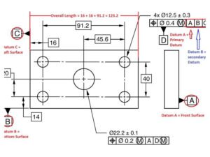
Common categories of geometric tolerance include:
| Category | What It Controls | Common Characteristics | Datum Needed |
|---|---|---|---|
| Form | Shape of a single feature | Straightness, flatness, circularity, cylindricity | No |
| Profile | A curve or surface against its ideal outline | Profile of a line, profile of a surface | Optional |
| Orientation | Direction relative to a datum | Parallelism, perpendicularity, angularity | Yes |
| Location | Position relative to a datum | Position | Yes |
| Runout | Variation of a rotating part about an axis | Circular runout, total runout | Yes |
General Tolerance
General tolerances apply to dimensions that do not have individual tolerances specified on the drawing. They provide a consistent way to control non-critical dimensions without adding a separate tolerance callout to every feature.
For example, a drawing may specify a general tolerance standard and tolerance class in its title block. Dimensions without individual tolerance requirements are then evaluated according to that standard, provided the standard applies to the relevant features.
General tolerances simplify drawings and reduce unnecessary annotation. They are often suitable for overall dimensions, non-critical steps, and features whose variation does not significantly affect assembly or performance.
They do not replace individually specified tolerances for critical features. A precision hole, sealing surface, or locating feature may require tighter tolerances than the general tolerance permits. The drawing should also identify the applicable standard and class clearly; a general tolerance should not be assumed without a stated requirement.
Tolerance Fits
Tolerance fits describe the relationship between two mating components, usually a hole and a shaft. Their size limits determine whether the assembled parts have clearance, interference, or a fit that may produce either condition.
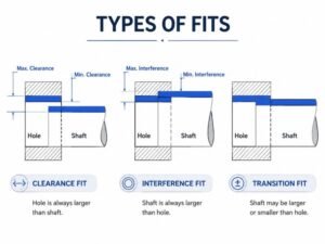
- Clearance Fit: The hole is always larger than the shaft within the specified limits. The resulting gap allows assembly and, where required, relative movement. Clearance fits are common in sliding components, rotating shafts, and removable assemblies.
- Interference Fit: The shaft is always larger than the hole within the specified limits. Assembly requires force, thermal expansion, or another suitable method. The resulting contact pressure can secure components without separate fasteners.
- Transition Fit: The permitted size ranges overlap, so the assembled parts may have either a small clearance or a small interference. Transition fits are useful when accurate positioning is required, and the assembly should have limited looseness.
For a more detailed explanation of different fit types, their classifications, and how to choose the right fit for your application, read our guide to types of fits.
How to Choose Suitable Engineering Tolerances?
Choosing engineering tolerances requires balancing functional requirements with manufacturing capability. A tolerance should be tight enough to ensure the part works as intended, but not tighter than necessary.
- Start with the function. Decide whether the feature must fit, align, move, seal, or only look right.
- Separate critical from non-critical features. Tight tolerances belong only where function depends on them.
- Check process capability. CNC machining, injection molding, and 3D printing reach different levels of accuracy. For plastics, include shrinkage, warpage, moisture absorption, and thermal expansion.
- Check inspection capability. The measuring device should resolve aboutone-tenthh of the tolerance. For plastic parts, consider temperature, humidity, and time since molding.
- Review early with the supplier. A design-for-manufacturing review confirms feasibility before tooling or production.
- Make the drawing clear. Put a general tolerance note in the title block, mark only the critical dimensions individually, and give datums.
How Does Engineering Tolerance Affect Manufacturing Cost?
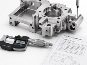
Tolerance has a direct effect on manufacturing cost because tighter requirements generally reduce the range of acceptable production outcomes. Meeting those requirements may require more precise equipment, additional process control, slower machining, improved tooling, or more detailed inspection.
For CNC-machined parts, tighter tolerances may require additional finishing passes, more stable workholding, tool-wear compensation, and temperature control. In injection molding, tight dimensional requirements may require better control of material drying, melt temperature, mold temperature, packing pressure, cooling, and mold condition. The necessary controls depend on the resin, geometry, and specified tolerance.
Tight tolerances can also increase the risk of rejected parts and rework. If a feature is functionally non-critical, specifying an unnecessarily tight tolerance may add cost without improving product performance.
The relationship is not identical for every feature or process. A small, accessible machined feature may be relatively easy to control, while a large molded component with uneven wall thickness may be difficult to keep dimensionally stable.
What Is Tolerance Stack-Up?
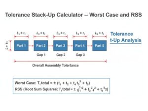
Tolerance stack-up is the combined effect of individual tolerances in an assembly. Each part can be within its own limits while the assembled dimension is outside the requirement. Consider three plates stacked together, each 10 ±0.1 mm. The assembly height can range from 29.7 to 30.3 mm.
| Method | Approach | Result for This Example | Notes |
|---|---|---|---|
| Worst-case | Assume all parts at their limits and add them | ±0.30 mm (29.70 to 30.30 mm) | Guarantees assembly, but requires tighter tolerances and higher cost; suited to safety-critical cases |
| Statistical (RSS) | Take the square root of the sum of the squared tolerances | √(0.1² + 0.1² + 0.1²) ≈ ±0.17 mm (about 29.83 to 30.17 mm) | Assumes it is unlikely that all parts sit at their limits at once; allows wider tolerances |
Conclusion
Dimensional tolerance controls size, geometric tolerance controls form, orientation, and location, general tolerances give unmarked dimensions a default rule, and tolerance fits set how two parts go together. Stack-up connects them across a full assembly. Engineering tolerance should be based on the function of each feature and on what the process can reliably produce, and a smaller number does not mean a better one. If you are preparing a molded part, send us your drawing with the critical dimensions and fit requirements marked. We can review whether the tolerances are workable for injection molding before tooling begins and suggest changes where needed.