
No CNC machine can produce two parts with perfectly identical dimensions. Even on the same machine, running the same program, measurements will always drift by a small amount. This is why CNC machining tolerances exist. The standard tolerance held across most CNC shops is around ±0.005 in (0.127 mm), which is roughly the width of a couple of human hairs. That small a gap rarely matters. The real question is knowing when it does, and how tight a tolerance actually needs to be.
This guide walks through what tolerances are, the main types you will encounter, and how to set CNC machining tolerances in a way that protects part function without inflating cost.
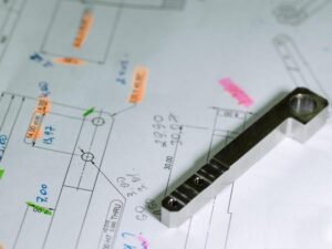
What Are CNC Machining Tolerances
CNC machining tolerances are the permissible range of deviation between a part’s finished dimensions and its specified nominal values, expressed as an upper and lower limit around a target measurement.
Rather than a target to aim for, a tolerance is a boundary the finished part must stay within. It offers a shared, measurable standard for “correct,” which is what makes consistent quality and interchangeable parts possible.
For example, a callout of Ø10.00 mm ± 0.05 mm means the hole is designed to be 10 mm in diameter, but anything between 9.95 mm and 10.05 mm is considered acceptable.
Common Types of CNC Machining Tolerances
CNC machining tolerances are generally expressed in one of a few standard formats, each suited to different kinds of dimensions and fits. The table below summarizes the main types.
| Type | What It Defines | Typical Use Case |
|---|---|---|
| Limit tolerance | An upper and lower bound the dimension must fall between (e.g. 25.0–25.1 mm) | General dimensioning where a clear min/max range is easiest to specify |
| Unilateral tolerance | Deviation allowed in only one direction from the nominal value (e.g. 20 +0.00/-0.05 mm) | Shaft and bore fits, where exceeding the limit in one direction would prevent assembly. |
| Bilateral tolerance | Deviation allowed symmetrically on both sides of the nominal value (e.g. 20 ±0.05 mm) | The most common format for general-purpose dimensions |
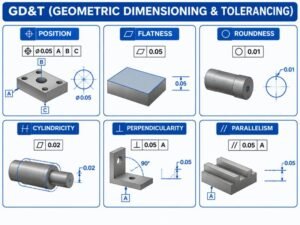
| GD&T | Controls not just size but geometric characteristics such as position, flatness, or roundness | High-precision assemblies where fit depends on geometry as well as dimension |
Limit, unilateral, and bilateral tolerances all describe how far a single dimension can vary. GD&T goes a step further by also governing the shape and spatial relationship of a feature. For example, a hole might sit within its size tolerance but still be positioned incorrectly relative to the rest of the part. It’s worth noting that for parts where geometry, not just size, determines whether the assembly works.
A Common Misconception About CNC Machining Tolerances: Tighter Isn’t Always Better
A tight tolerance on an individual part says something about how precisely that one feature was machined. It does not automatically translate into a better-performing product. Product quality is ultimately determined by how well parts work together as an assembly, not by how narrow each individual tolerance is.
As tolerances tighten, machining cost, cycle time, and scrap rate all climb, often steeply, because more of the batch falls outside spec and secondary operations like grinding or EDM become necessary. At the same time, tolerances that are too loose can just as easily cause assembly failures and rework. The goal isn’t the tightest tolerance possible; it’s the tolerance that matches what the part actually needs to function correctly.
How to Set Reasonable CNC Machining Tolerances
The following design-stage decisions can control cost while still protecting fit and function:
1. Design in Reasonable Clearance
When two parts don’t require a tight, no-play fit, avoid specifying tighter tolerances than necessary. A small amount of clearance can make assembly easier and reduce machining requirements without affecting performance.
For example, a standard screw mounting hole usually does not need to match the screw diameter exactly. Instead of specifying a tight tolerance on the hole size, designers can use a clearance hole that provides enough room for assembly while maintaining secure fastening.
2. Simplify Assembly Relationships
Every dimension in an assembly’s tolerance chain adds to the cumulative tolerance the final assembly has to absorb. Reducing the number of mating parts or dimensions involved in a critical fit shrinks that cumulative variation, which means each individual part can carry a looser tolerance while the assembly still comes together correctly.
3. Use Positioning Features
Locating pins, datum holes, or reference edges help control the dimensions that directly affect alignment, while other features can often use looser tolerances.
For example, two plates connected by screws do not need every screw hole to precisely locate the parts. Adding two locating pins can control the exact position of the plates, while the screw holes only need enough clearance for fastening. This allows tighter tolerances to be applied only where alignment matters.
4. Replace Plane-to-Plane Fits with Point or Line Contact Where Possible
When two flat surfaces need to mate or slide against each other, warping, surface roughness, and machining variation can make a precise fit difficult to maintain. Where possible, redesigning the contact area can reduce tolerance requirements.
For example, using localized contact points or guide features instead of relying on two large surfaces to align perfectly can improve reliability while avoiding unnecessarily tight flatness tolerances.
What Else Affects Achievable CNC Machining Tolerances
Even with a well-chosen tolerance, a few practical factors influence how easily CNC machining tolerances can actually be held:
- Material: Soft materials tend to flex under cutting force, making tight tolerances harder to hold consistently. Abrasive materials wear tooling faster, which can cause dimensions to drift over a production run. If you need to learn more about material selection, you can refer to our guide to CNC machining materials.
- Process: Some tolerances are only achievable with secondary operations such as grinding or wire EDM, which add time and cost beyond standard milling or turning. To learn more related information, please look at the article about CNC machining types.
- Inspection: Tighter tolerances require more precise (and more expensive) measurement equipment and take longer to verify, which adds to per-part cost even before machining is considered.
Partner with Jiangzhi for Precision CNC Machining
The most cost-effective approach to CNC machining tolerances is also the simplest: apply tight tolerances only to the features where fit and function genuinely demand them, and let everything else default to a standard, looser tolerance. This keeps assemblies working reliably without paying for precision that never gets used.
Jiangzhi provides precision CNC machining services with professional engineering support and quality control to help customers achieve reliable, cost-effective custom parts. Our team can help optimize your tolerance requirements and deliver parts that meet your project needs. Contact Jiangzhi today to discuss your CNC machining project.


