Are your injection molded parts suffering from inconsistent wall thickness, frequent parting line flash, or premature dimensional drift? In many cases, these quality issues are not caused by material flow or cooling parameters, but by the mechanical foundation of the mold: the injection mold guide system.
During high-speed production cycles, even a microscopic misalignment between the core and cavity can compromise part integrity, accelerate tooling wear, and lead to costly scrap rates. The guide system—typically consisting of precision-machined guide pins and bushings—serves as the critical alignment structure that ensures the mold halves close with perfect repeatability, shot after shot.
What Is an Injection Mold Guide System?
An injection mold guide system is a mechanical alignment structure installed between the two halves of an injection mold. Its main purpose is to guide the mold during closing and opening, maintain accurate alignment between the core and cavity, and prevent unwanted lateral movement.
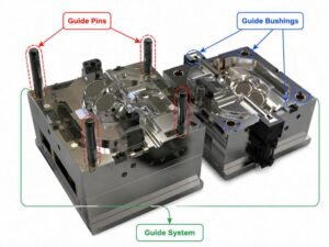
The guide system usually consists of precision components such as guide pins and guide bushings. When the mold closes, the guide pins enter the guide bushings and control the movement direction of the mold plates. This process ensures that the cavity and core are positioned correctly before injection pressure is applied.
In injection molding, the mold experiences thousands or even millions of opening and closing cycles. Without a reliable guiding structure, repeated movement can gradually create alignment deviations. These deviations may result in flash defects, dimensional inconsistencies, and damage to precision mold components.
Main Components of Injection Mold Guide System
The injection mold guide system mainly relies on two core precision components: guide pins and guide bushings. These components work together to control mold movement, maintain alignment accuracy, and reduce wear during repeated injection molding cycles. Additional supporting elements help improve durability and maintain stable mold operation.
| Guide Components | Function |
|---|---|
| Guide Pin (Leader Pin) | A precision cylindrical component installed on one mold half. It guides the mold halves during closing and helps maintain alignment between the core and cavity. Guide pins are typically made from hardened steel to provide wear resistance and long-term dimensional stability. |
| Guide Bushing (Leader Bushing) | A precision sleeve that works with the guide pin to provide smooth and accurate guiding movement while reducing friction and wear. Common types include plain guide bushings for standard applications and ball bearing guide bushings for high-precision molds requiring lower friction and improved guiding performance. |
| Wear Plates / Wear Strips | Supporting components used to reduce friction and wear between moving mold parts, especially in large molds or molds with sliding mechanisms. They help maintain stable movement and extend mold service life. |
How Does an Injection Mold Guide System Work?
During the mold closing process, the moving mold approaches the stationary mold. Before the cavity and core fully contact each other, the guide pins enter the guide bushings. As the mold continues closing, the guide system maintains alignment between the mold plates. The core and cavity reach the designed position, allowing the parting surfaces to close evenly. After cooling, the mold opens, and the guide components continue to support smooth movement during the next production cycle.
Guide System vs Positioning System: What Is the Difference?
Although the terms are sometimes used together, an injection mold guide system and a mold positioning system serve different purposes.
While both contribute to mold accuracy, they function at different stages of the molding cycle and handle different force loads.
| Feature | Guide System |
|---|---|
| Primary Objective | Controls continuous linear motion during opening/closing. |
| Active Stage | Active throughout the entire stroke of mold travel. |
| Load Handling | Handles guiding loads and weight displacement. |
Common Mold Problems Caused by Poor Guide System Design
A poorly designed or improperly maintained injection mold guide system can create various production issues. Since injection molds operate under repeated mechanical movement, small alignment problems can become more serious over time.
Mold Misalignment
Mold misalignment is one of the most common problems caused by an inadequate guiding system. Possible causes include incorrect guide pin and bushing selection, excessive clearance between components, insufficient guide components for large molds, poor machining accuracy, and wear caused by long-term operation.
When the core and cavity do not align correctly, molded parts may have dimensional variations or uneven wall thickness. In precision applications, even minor alignment errors can affect assembly performance.
Flash Defects on Molded Parts
A poor guide system may allow mold halves to shift slightly during closing or injection. This creates an uneven parting line condition where plastic can enter the gap. Flash defect occurs when molten plastic escapes through unwanted gaps between mold components.
Common results include visible flash on the molded part, additional trimming requirements, and increased rejection rates. Maintaining accurate mold alignment helps reduce the risk of flash caused by mold positioning issues.
Increased Mold Wear
Guide components experience repeated sliding and mechanical loads during production. If the design is incorrect or the components are damaged, excessive friction and side loading may occur. This can accelerate wear on guide pins, guide bushings, mold plates, and core and cavity surfaces.
Regular inspection and proper lubrication can help maintain guide system performance.
Damage to Precision Mold Components
When the guide system cannot maintain proper alignment, other mold components may absorb additional stress. Potentially affected components include mold inserts, cavity blocks, core pins, slides, and ejector components.
Repairing these components is usually more expensive than replacing worn guide components. Therefore, proper guide system design is an important part of mold reliability.
How to Select and Design the Right Guide System?
A suitable guide system should provide stable alignment, reduce wear, and maintain consistent performance throughout the mold’s service life. Selecting and designing the right injection mold guide system requires consideration of several factors, including mold size, production requirements, precision requirements, and operating conditions.
Consider Mold Size and Weight
Large molds require stronger guiding structures because they experience higher mechanical loads during movement. For larger molds, usually consider larger diameter guide pins, additional guide locations, higher strength materials, and improved support structures. The number and size of guide components should match the mold dimensions and operating conditions.
Consider Required Precision Level
Different applications require different alignment accuracy. For standard injection molded parts, conventional guide pins and bushings may be sufficient. However, precision parts used in industries such as automotive, electronics, and medical applications often require tighter control. High-precision molds may require improved machining tolerances, precision positioning components, and wear-resistant materials.
Consider Production Volume
Production volume affects material selection and component durability requirements. For high-volume production, guide components should provide high wear resistance, stable dimensional performance, and long service intervals.
For prototype or low-volume molds, standard guide components may provide sufficient performance while controlling tooling costs.
Match the Guide System with Mold Structure
The mold structure also affects guide system design. Factors to consider include multi-cavity mold layout, large inserts, sliding mechanisms, complex mold actions, and mold opening stroke. A complex mold design may require additional alignment structures to maintain stable operation.
Select Suitable Materials and Surface Treatments
Guide pins and guide bushings commonly use hardened steel materials because they require good wear resistance and dimensional stability. Important material considerations include hardness, surface finish, corrosion resistance, and friction characteristics. Proper lubrication and maintenance are also necessary to reduce wear and maintain smooth movement.
Conclusion
The injection mold guide system is a key structure for maintaining mold alignment and ensuring stable injection molding operations. A well-designed mold guiding system helps prevent common issues such as mold misalignment, flash defects, excessive wear, and component damage.
As a specialized custom injection molding and tooling manufacturer, Jiangzhi provides comprehensive DFM (Design for Manufacturability) analysis, mold flow simulations, and precision tooling development. Have a custom injection molding project? Contact our engineering team with part drawings, material requirements, and production expectations. Jiangzhi will help to evaluate the appropriate guide system design and improve overall mold performance.