
A press fit joins two parts by forcing a shaft into a slightly smaller hole, creating enough friction to hold the assembly together without bolts, adhesives, or welding. Bearings, gears, pins, and bushings all commonly rely on this method.
A reliable press fit comes from a design process. The required holding force, the tolerance class, the material pairing, the surrounding geometry, and the assembly method are decisions that build on one another. This guide walks through that process step by step, then covers verification and the most common design failures.
What Is a Press Fit
A press fit is an interference joint, one of the primary types of fit. The shaft is manufactured slightly larger than the hole it fits into. Forcing the parts together deforms both slightly at the interface, producing contact pressure. This pressure creates the friction that resists axial movement and rotation.
“Interference fit” describes the dimensional relationship between the parts. “Press fit” describes an interference joint assembled through mechanical force, as opposed to a shrink fit, which uses temperature change to reach the same result. This distinction matters as the assembly method becomes its own design choice.
The Press Fit Design Process
A press fit’s strength, its required assembly force, and its long-term reliability all trace back to five decisions, made in order:
1. Define the functional requirement
2. Calculate the interference range
3. Select a tolerance class
4. Design the material pairing and geometry
5. Select an assembly method
Step 1: Define the Functional Requirement
The joint’s role in the assembly should be clear before any dimension is chosen. A press fit might need to be permanent or serviceable, resist axial pull-out, transmit torque, or simply locate a part accurately with little load. These requirements vary widely in magnitude, and defining them first avoids two common mistakes: too much interference, which raises stress and assembly force for no benefit, and too little, which produces a joint that slips.
Step 2: Calculate Interference
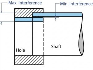
Because both the shaft and hole carry manufacturing tolerances, interference is a range, not a single value. Minimum interference pairs the smallest shaft with the largest hole. Maximum interference pairs the largest shaft with the smallest hole.
Minimum interference must satisfy the requirement from Step 1. Maximum interference sets the limit on stress and assembly force.
A larger interference produces higher contact pressure between the shaft and hole, and that pressure generates the joint’s holding force. Geometry and material affect the outcome too: a thicker hub or stiffer material develops more pressure from the same interference than a thinner hub or a softer material.
Higher pressure raises the force needed to press the parts together and the torque the joint can resist, along with the stress on both parts. A longer engagement length between the shaft and hole increases holding capacity and assembly force together.
Temperature matters whenever the shaft and hub are different materials, or the assembly runs across a wide temperature range, since materials expand and contract at different rates. A fit that holds at room temperature can loosen at operating temperature if this is not checked early.
Step 3: Select a Tolerance Class
Standards such as ISO 286 translate a calculated interference range into a manufacturable tolerance class. Most press fits use the hole-basis system, holding the hole at a fixed zone (commonly H7) and varying the shaft’s zone to set the interference.
| ISO Designation | Interference Level | Typical Use |
|---|---|---|
| H7/p6 | Light | Accurate location, lightly loaded hubs |
| H7/r6 | Moderate | Gears, hubs, shaft-mounted parts |
| H7/s6 | Higher | Permanent, higher-load joints |
| H7/u6 | Heavy | Highly loaded joints, often shrink fit |
Example: 25 mm H7/p6 fit
H7 hole: 25.000 to 25.021 mm
p6 shaft: 25.022 to 25.035 mm
Minimum interference: 0.001 mm
Maximum interference: 0.035 mm
This range is checked against Step 1’s requirement. If it falls short, a higher-interference class is selected instead.
Step 4: Design the Material Pairing and Geometry
Material Pairing: Modulus and yield strength determine how much stress a given interference produces. Softer materials, including many polymers and elastomers, need more interference for the same contact pressure and are more prone to creep and stress relaxation, which lowers retention over time. Dissimilar materials expand at different rates, so their fit should be checked across the full operating temperature range.
Hub Wall Thickness and Shaft Construction: A thick hub develops higher interface pressure from the same interference. A thin hub expands more easily but carries higher hoop stress and a greater risk of cracking. A hollow shaft is more compliant than a solid one. Nearby features such as shoulders, keyways, or sudden section changes concentrate stress and need separate attention.
Engagement Length: A longer engagement increases contact area and load resistance, along with press-in force and the importance of alignment. Too short an engagement risks weak retention; too long adds cost without benefit.
Lead-in Geometry and Alignment: Chamfers and pilot features let the shaft begin engaging before full interference develops, reducing damage and force spikes at first contact. Coaxial alignment throughout the pressing stroke prevents scoring and uneven contact.
Surface Finish: Rough surfaces flatten under pressing load, reducing effective interference below the measured dimension. Overly rough surfaces raise assembly force and galling risk; overly smooth or heavily lubricated surfaces reduce retention. Coatings such as anodizing or plating change final mating dimensions and should be checked in the finished condition.
Step 5: Select an Assembly Method
Mechanical pressing applies axial force while both parts stay near their normal dimensions. It covers most small and medium interference joints, using arbor presses for light work and hydraulic or servo presses for higher force and process control.
Thermal assembly changes temperature to temporarily reduce interference. Heating the hub (shrink fit) expands the bore; cooling the shaft (cold fit) contracts it; combining both allows larger interference values. This method suits cases where mechanical force alone would need excessive press capacity or risk galling, though cold fitting brings condensation risk and shrink fitting can damage heat-sensitive coatings.
Hydraulic or oil-injection mounting introduces pressurized oil at the interface to reduce friction, allowing assembly under much lower force. It is generally reserved for large interference joints and heavy industrial assemblies.
The interference and geometry chosen earlier largely determine which method is practical, which makes assembly method part of the design rather than a downstream manufacturing detail.
Verifying the Press fit Design
Because the mating surfaces become inaccessible once assembled, verification belongs inside the design process.
| Characteristic | Inspection Method |
|---|---|
| Shaft diameter | Outside micrometer |
| Bore diameter | Bore gauge or air gauge |
| Roundness | Roundness measuring instrument |
| Surface roughness | Profilometer |
| Assembly force | Instrumented press or load cell |
| Insertion depth | Press displacement monitoring |
Checking dimensions before assembly confirms the interference falls within range. Monitoring force and displacement during assembly flags misalignment or incomplete seating before it becomes a field failure.
Common Design Failures
The five steps describe what a sound press fit design looks like. Looking at how press fits actually fail shows what happens when one of those steps is skipped or handled carelessly, and makes each step’s importance easier to see in practice.
Excessive press force usually comes from interference set too high for the material and geometry, often combined with a missing chamfer or poor lubrication.
Slipping under load results from minimum interference calculated without a clear functional requirement, or a requirement that changed after the design was finalized.
Hub cracking happens when interference exceeds the material’s allowable stress, especially with thin walls or brittle materials. Higher interference does not produce a stronger joint on its own; it produces a joint closer to its material limit.
Galling occurs when surfaces slide under high pressure without adequate lubrication or compatible hardness.
Loosening in service traces back to differential thermal expansion left unchecked, or to creep and stress relaxation in lower-modulus materials.
Press Fit vs. Other Joining Methods
Press fits are one of several ways to join two parts without welding, alongside snap fits, threaded fasteners, and adhesive bonding. The right choice depends on load, whether the joint needs to come apart again, and how much added hardware the assembly can tolerate.
| Method | Load Capacity | Disassembly | Added Parts | Typical Use |
|---|---|---|---|---|
| Press fit | High axial and torsional retention | Difficult, often damages parts | None | Bearings, gears, bushings, pins |
| Snap fit | Lower | Easy, designed for repeated assembly | None | Plastic housings, consumer products |
| Threaded fastener | High | Easy | Bolt, screw, or nut | Serviceable assemblies, structural joints |
| Adhesive bonding | Depends on bond area and material | Very difficult | None, but adds cure time | Dissimilar materials, sealing joints |
Conclusion
A press fit’s reliability comes from calculating interference against a real functional requirement, translating that into a tolerance class that respects both strength and manufacturability, pairing it with compatible materials and geometry, and assembling it with a suited method. These five connected decisions separate a press fit that lasts the life of a product from one that becomes a service call.
Holding the tolerances this process calls for, often within a few thousandths of a millimeter, depends on the machining process used to produce the shaft and bore. Jiangzhi’s CNC machining services hold these tolerances consistently across production volumes, from prototypes through full production runs, across metal and engineering plastic components alike.


